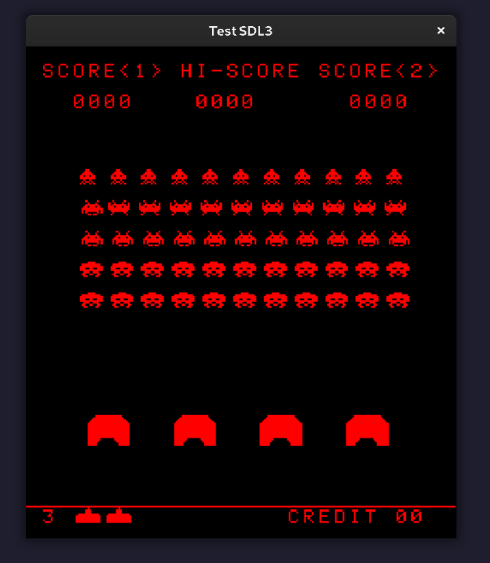
The Demo Screen
With three other teammates, I have been working on an emulator of Intel’s 8080 microprocessor that will play Space Invaders. Here is the repository. So, in addition to emulating the 8080 in software, we had to provide peripheral hardware emulation: input, audio, and video. In this post, I’m going to walk through how the video component works, paying special attention to the code we used to translate video data from the 8080’s memory to the game window. We wrote it in C++, but the information is language agnostic. This process was made a lot easier than it would have been thanks to the hardware information on emulator enthusiast website Computer Archaeology. There are three components to cover:
- Creating the display.
- Prompting the 8080 to update the video data.
- Updating the display with that video data.
Creating the Display
We used SDL3 for all of our peripheral devices to the 8080. I highly recommend going through Mike Shah’s SDL3 tutorials on YouTube. Between Mike’s tutorials and the source code for the example snake game provided by the SDL3 website, it was a fairly straightforward process.
First, initialize SDL:
if (!SDL_Init(SDL_INIT_VIDEO | SDL_INIT_EVENTS | SDL_INIT_AUDIO)) {
  SDL_Log("Initialization failed!");
  return SDL_APP_FAILURE;
}
Next, set up the display structures: a window and a renderer. The Space Invaders arcade cabinet uses a screen 224 pixels wide by 256 pixels high.
// These are in our main.cc file.
constexpr int kWindowWidth = 224;
constexpr int kWindowHeight = 256;

// This is in a GameWindow class.
SDL_Window* window_;
SDL_Renderer* renderer_;

if (!SDL_CreateWindowAndRenderer("Test SDL3", window_width, window_height,
                                 SDL_WINDOW_RESIZABLE, &window_,
                                 &renderer_)) {
  SDL_Log("Failed to create window and renderer.");
  std::exit(1);
}
Next, set the logical presentation mode to letterbox, which will scale the display to the window as it is resized without distorting the ratio.
SDL_SetRenderLogicalPresentation(renderer_, window_width, window_height,
                                 SDL_LOGICAL_PRESENTATION_LETTERBOX);
Finally, set the renderer’s draw color to black, make it opaque, and clear and present it:
SDL_SetRenderDrawColor(renderer_, 0, 0, 0, SDL_ALPHA_OPAQUE);
SDL_RenderClear(renderer_);
SDL_RenderPresent(renderer_);
Updating Video Data
As explained by Computer Archeology, the display hardware would use the 8080’s interrupt system to trigger a refresh of the video data twice per refresh: once when the raster beam The cabinet’s display was a raster screen that ran at 60hz. A beam would travel left-to-right across the screen one row after another. When the beam was near the middle of the this process, it would trigger the first interrupt. At the end of the screen, it would trigger a second. For our purposes, with a new frame expected approximately every 16.67ms, we decided to trigger each interrupt after about 8ms.
As explained in Intel’s /8080 Programmer’s Manual/, the RST instructions work with the interrupt system (p. 37).
Each RST has a three-bit exp value, which comprises bits 5, 4, and 3 of the opcode itself.
“The interrupting device calls a particular RST instruction,” which transfers control to a subroutine.
How do we know which RST instruction to call for a given device?
From computer archaeology: “the system gets RST 8 when the beam is near the middle of the screen and RST 10 when it is at the end.”
The exp for the first is 1, and for the second it is 2.
Although the instructions are RST 1 and RST 2, they’ll also be referred to by the hexadecimal values that set the correct bit in the exp bits of the opcode.
For RST 1, it’s RST 8 (0x8 = 0b0000'1000), and for RST 2, it’s RST 10 (0x10 = 0b0001'0000).
Once either 8ms has passed or a HLT (for “halt”) instruction puts the CPU into a stopped state to await an interrupt, the main loop stops the CPU from stepping through memory, and the appropriate opcode is pushed onto an interrupt queue.
This could have been accomplished by directly executing the RST instruction’s method.
However, by keeping it in the conventional order of execution as for non-interrupt opcodes, we were able to rely on our same debugging code in the CPU’s execute() method.
Once the 8080 has RST 1 and RST 2 interrupting its flow of execution, video data will get updated.
Updating the display with video data
After the second interrupt, the main loop calls two methods. The first reads the video data and creates a collection of pixels that need to be set in the display. The second passes that collection to the GameWindow object to update the renderer and present it to the window. That first step is where the bulk of the challenge lies.
Video data occupies a section of RAM from 0x2400 to 0x3FFF. Each bit corresponds to a pixel. However, the physical display used by the arcade cabinet was 256 wide by 224 height, and it was rotated counter-clockwise 90 degrees for the experienced 224 wide by 256 tall screen. Accordingly, the mapping of bits in video ram to point coordinates in the SDL window isn’t a simple top-left to right and downwards trajectory. Instead, while our algorithm traverses the video ram in a linear fashion, it does so while traversing the game window’s points from bottom left to top, left to right. Here’s the video memory rotated to match the screen orientation, where the bracketed numbers are the bits:
0x241F[7] ...           0x3FFF[7]
...
0x2402[1] ...
0x2402[0] 0x2422[0] ... ...
0x2401[7] 0x2421[7] ... 0x3FE1[7]
...
0x2400[2] 0x2420[2] ... 0x3FE0[2]
0x2400[1] 0x2420[1] ... 0x3FE0[1]
0x2400[0] 0x2420[0] ... 0x3FE0[0]
There are 256 rows of pixels: 32 bytes * 8 bits. If each “row” in the outer for lop corresponds to a byte in memory, then there are 32 such rows.
Three nested loops keep track of the column (x coordinate), the row, and the bit (y coordinate).
It keeps track of the bit in video memory with a separate variable, from which the correct byte can be calculated using integer division.
The function takes a reference to a vector of SDL_FPoint structs as well as a span view of just the 7168 bytes of video memory in the 8080’s total 64kb of memory.
void DecodePixels(std::vector<SDL_FPoint>& points,
                  std::span<unsigned char, 7168> video_data) {
  // v_idx will increment for each bit, from 0 to (256*224 - 1).
  uint16_t v_idx{0};
  points.clear();

  // Start at bottom left coordinate.
  for (int col = 0; col < 224; col++) {
    for (int row = 32; row > 0; row--) {
      for (int bit{0}; bit < 8; bit++) {
        // Calculate which byte the loop is on by reducing the pixel number by a
        // factor of 8.
        uint16_t video_byte = v_idx / 8;

        if (video_data[video_byte] & (0x01 << bit)) {
          int y = (row * 8) - 1 - bit;
          points.push_back(SDL_FPoint{.x = static_cast<float>(col),
                                      .y = static_cast<float>(y)});
        }

        v_idx++;
      }
    }
  }
}
This took some doing! Walk through one or two bits/pixels by hand, tracing the position in memory and the coorindate in the window, and it should click.